RS-LLEG
6 axes · RS-485 HALF-DUPLEX
Power: HN01_TORSO_POWER_SPINE | HN01_L_LEG_POWER
Data: HN01_TORSO_DATA_SPINE | HN01_L_LEG_DATA
Stall endpoint sum: 24.20 A
PRELIMINARY - NOT APPROVED FOR CONNECTION, FABRICATION, MOTION OR ENERGIZATION
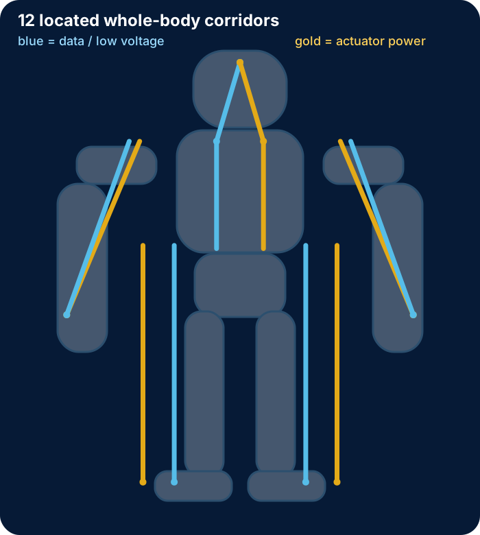
Eight protected segment candidates, 25 actuator drops, 33 connector boundaries, and 12 located corridors.
6 axes · RS-485 HALF-DUPLEX
Power: HN01_TORSO_POWER_SPINE | HN01_L_LEG_POWER
Data: HN01_TORSO_DATA_SPINE | HN01_L_LEG_DATA
Stall endpoint sum: 24.20 A
6 axes · RS-485 HALF-DUPLEX
Power: HN01_TORSO_POWER_SPINE | HN01_R_LEG_POWER
Data: HN01_TORSO_DATA_SPINE | HN01_R_LEG_DATA
Stall endpoint sum: 24.20 A
3 axes · RS-485 HALF-DUPLEX
Power: HN01_TORSO_POWER_SPINE | HN01_L_ARM_POWER
Data: HN01_TORSO_DATA_SPINE | HN01_L_ARM_DATA
Stall endpoint sum: 6.90 A
3 axes · RS-485 HALF-DUPLEX
Power: HN01_TORSO_POWER_SPINE | HN01_R_ARM_POWER
Data: HN01_TORSO_DATA_SPINE | HN01_R_ARM_DATA
Stall endpoint sum: 6.90 A
1 axes · RS-485 HALF-DUPLEX
Power: HN01_TORSO_POWER_SPINE
Data: HN01_TORSO_DATA_SPINE
Stall endpoint sum: 4.40 A
2 axes · TTL HALF-DUPLEX
Power: HN01_TORSO_POWER_SPINE | HN01_L_ARM_POWER
Data: HN01_TORSO_DATA_SPINE | HN01_L_ARM_DATA
Stall endpoint sum: 1.76 A
2 axes · TTL HALF-DUPLEX
Power: HN01_TORSO_POWER_SPINE | HN01_R_ARM_POWER
Data: HN01_TORSO_DATA_SPINE | HN01_R_ARM_DATA
Stall endpoint sum: 1.76 A
2 axes · TTL HALF-DUPLEX
Power: HN01_TORSO_POWER_SPINE | HN01_HEAD_POWER_BRANCH
Data: HN01_TORSO_DATA_SPINE | HN01_HEAD_BRANCH
Stall endpoint sum: 1.76 A
| Route | Service | Centerline mm | Diameter mm | Minimum bend radius mm |
|---|---|---|---|---|
| HN01_TORSO_POWER_SPINE | ACTUATOR POWER | 170.0 | 14.0 | 70.0 |
| HN01_TORSO_DATA_SPINE | DATA/LOW VOLTAGE | 170.0 | 10.0 | 50.0 |
| HN01_HEAD_BRANCH | DATA/LOW VOLTAGE | 126.4 | 10.0 | 50.0 |
| HN01_HEAD_POWER_BRANCH | ACTUATOR POWER | 126.4 | 8.0 | 40.0 |
| HN01_L_LEG_POWER | ACTUATOR POWER | 375.0 | 12.0 | 60.0 |
| HN01_L_LEG_DATA | DATA/ENCODER | 375.0 | 9.0 | 45.0 |
| HN01_L_ARM_POWER | ACTUATOR POWER | 280.6 | 10.0 | 50.0 |
| HN01_L_ARM_DATA | DATA/ENCODER | 279.2 | 8.0 | 40.0 |
| HN01_R_LEG_POWER | ACTUATOR POWER | 375.0 | 12.0 | 60.0 |
| HN01_R_LEG_DATA | DATA/ENCODER | 375.0 | 9.0 | 45.0 |
| HN01_R_ARM_POWER | ACTUATOR POWER | 280.6 | 10.0 | 50.0 |
| HN01_R_ARM_DATA | DATA/ENCODER | 279.2 | 8.0 | 40.0 |
Primary manufacturer documentation defines every actuator-side pin, all eight STM32 channel pins, the five isolated RS-485 and three TTL interface-device pinouts, and data-only JST PA connector candidates whose contact ranges include the planning conductor sizes. It does not release the assembled cables, received insulation O.D., crimp process, branch protection, routing durability, termination, EMC, or fault behavior.
Actuator pinouts · Bus assemblies · 25 drops · 33 boundaries · 12 corridors · Sources
50 Hz torque-producing current-equivalent traces.
Peak, P95, RMS and mean bounded envelopes.
Idle current, losses, gripping, transients, faults and thermal tests remain open.
physical power routes bound to pooled whole-body duty.
bus-domain loss and peak/RMS screens.
power-corridor bundle obligations.
released hot ratings or executed thermal tests.
One protected VDD/return pair runs from its protection channel to one actuator transition without an intermediate splice.
Every distal branch is represented at every upstream joint it must physically cross.
Rigid link-local channels stop before each axis; flexible dress-pack envelopes cover the nominal joint arcs.
The conflicting 25-board/45-piece Cicoil cascade receives no selection or procurement credit.
Full-range collision, pinch, torsion, flex life, derating, termination and physical proof are not complete.
Every actuator retains a dedicated positive and return pair with explicit trunk cores and cavities.
Protection moves to the pelvis, shoulder roots, waist bay and neck base.
The multi-core trunk candidate fits every circular corridor screen.
Every trunk binds to two dimensioned tangent circular guides at the cable-specific planning radius.
The fixed-pose tangent-radius calculations reproduce.
No continuous whole-limb path is eligible to cross a moving joint.
The successor separates rigid link channels from flexible joint bellows.
The STEP and GLB remain useful for endpoint traceability.