5
native PCB candidates on exact mounting axes
Project Button · whole-body E1 artifact
The complete humanoid now has a physical controls-only fixture candidate, not merely an E1 paragraph.
native PCB candidates on exact mounting axes
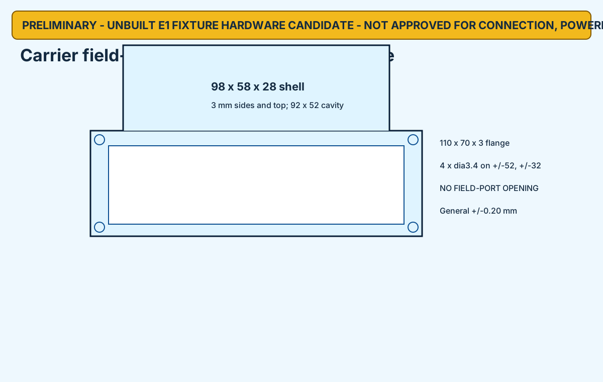
actuator-data field ports enclosed
actuator-power connectors, conductors, PDUs or actuators
built fixtures or authorized powered tests
| Stage | Installed | Physically absent | Execution |
|---|---|---|---|
| E1-A | MCU + SWD adapter | both carriers; every PDU; every actuator cable; every actuator | NOT EXECUTED |
| E1-B | MCU + both carriers + sealed covers + under-panel logic cables | all eight field cables; every PDU; every actuator power source; every actuator | NOT EXECUTED |
| E1-C | E1-B plus selected diagnostic watchdog in separately released adapter | all actuator interfaces remain inaccessible and unpowered | NOT EXECUTED |
| Port | Bus | Physical state |
|---|---|---|
| CARRIER_A-CH1 | RS-LLEG | ENCLOSED BY SCREW-RETAINED COVER; NO EXTERNAL OPENING |
| CARRIER_A-CH2 | RS-RLEG | ENCLOSED BY SCREW-RETAINED COVER; NO EXTERNAL OPENING |
| CARRIER_A-CH3 | RS-LARM | ENCLOSED BY SCREW-RETAINED COVER; NO EXTERNAL OPENING |
| CARRIER_A-CH4 | RS-RARM | ENCLOSED BY SCREW-RETAINED COVER; NO EXTERNAL OPENING |
| CARRIER_B-CH1 | RS-WAIST | ENCLOSED BY SCREW-RETAINED COVER; NO EXTERNAL OPENING |
| CARRIER_B-CH2 | TTL-LDIST | ENCLOSED BY SCREW-RETAINED COVER; NO EXTERNAL OPENING |
| CARRIER_B-CH3 | TTL-RDIST | ENCLOSED BY SCREW-RETAINED COVER; NO EXTERNAL OPENING |
| CARRIER_B-CH4 | TTL-HEAD | ENCLOSED BY SCREW-RETAINED COVER; NO EXTERNAL OPENING |
The watchdog board shown in CAD grounds the permit contact and keeps WDO/ENOUT local, but the board and cable are unbuilt and receive zero safety credit. Native board fabrication, received connector clearance, panel hardware, logic cables, supply limits, grounding, firmware flashing, HIL and independent approval remain open. This guide cannot authorize connection or power.
watchdog guide · open holds · PCB placements · mount axes · connector boundaries · candidate BOM
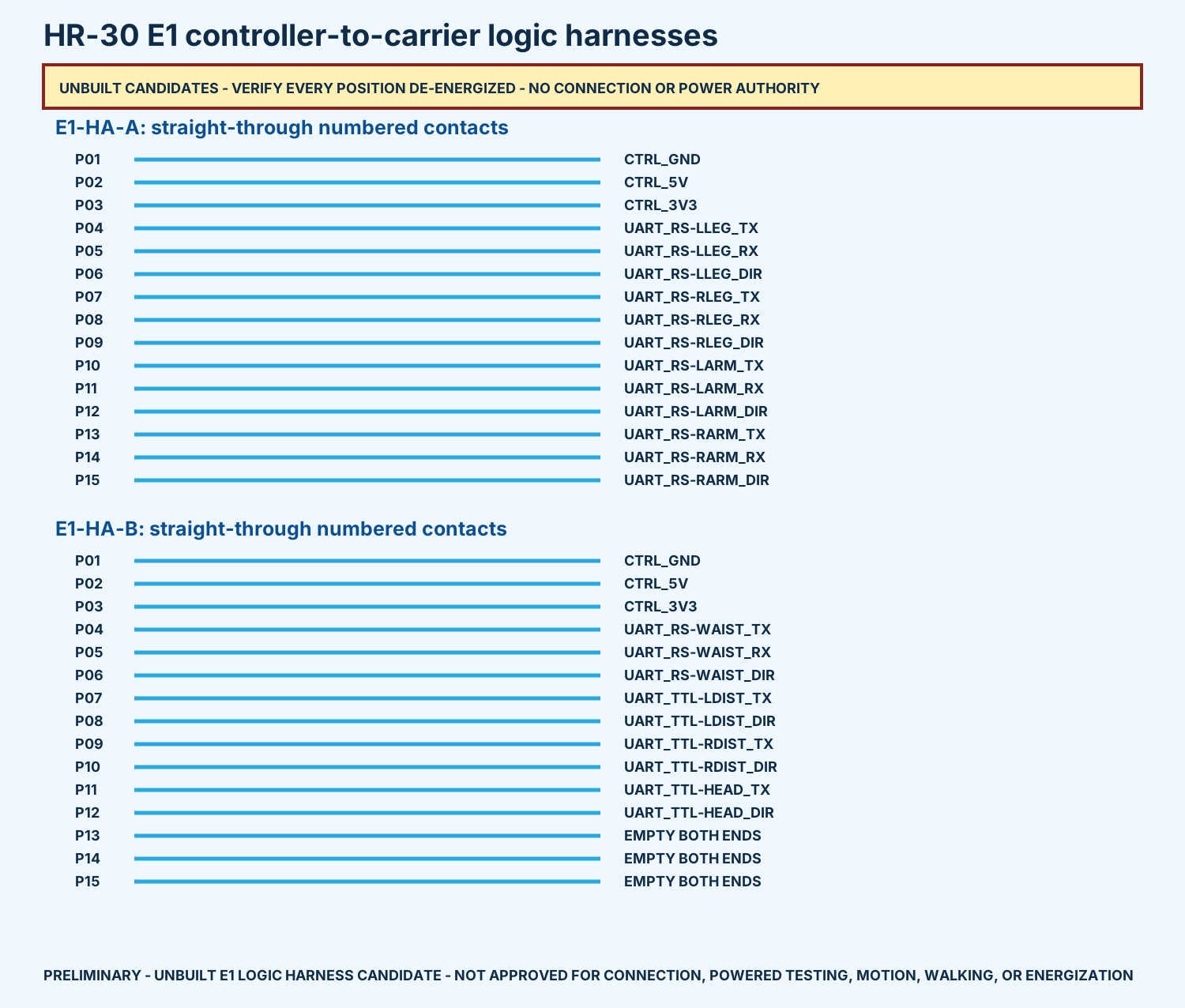
individually modeled, pin-bound conductors
candidate crimp contacts across four housings
carrier-B cavities deliberately empty
built, inspected, or authorized harnesses
integrated fixture STEP · harness-only STEP · assembly map
| Map | Net | Population | Wire | Cut length |
|---|---|---|---|---|
| E1-HA-A-01 | CTRL_GND | POPULATED BOTH ENDS | Belden 1852 BK005 | 320.000 |
| E1-HA-A-02 | CTRL_5V | POPULATED BOTH ENDS | Belden 1852 RD005 | 320.000 |
| E1-HA-A-03 | CTRL_3V3 | POPULATED BOTH ENDS | Belden 1852 YL005 | 320.000 |
| E1-HA-A-04 | UART_RS-LLEG_TX | POPULATED BOTH ENDS | Belden 1852 BL005 | 320.000 |
| E1-HA-A-05 | UART_RS-LLEG_RX | POPULATED BOTH ENDS | Belden 1852 WH005 | 320.000 |
| E1-HA-A-06 | UART_RS-LLEG_DIR | POPULATED BOTH ENDS | Belden 1852 OR005 | 320.000 |
| E1-HA-A-07 | UART_RS-RLEG_TX | POPULATED BOTH ENDS | Belden 1852 BL005 | 320.000 |
| E1-HA-A-08 | UART_RS-RLEG_RX | POPULATED BOTH ENDS | Belden 1852 WH005 | 320.000 |
| E1-HA-A-09 | UART_RS-RLEG_DIR | POPULATED BOTH ENDS | Belden 1852 OR005 | 320.000 |
| E1-HA-A-10 | UART_RS-LARM_TX | POPULATED BOTH ENDS | Belden 1852 BL005 | 320.000 |
| E1-HA-A-11 | UART_RS-LARM_RX | POPULATED BOTH ENDS | Belden 1852 WH005 | 320.000 |
| E1-HA-A-12 | UART_RS-LARM_DIR | POPULATED BOTH ENDS | Belden 1852 OR005 | 320.000 |
| E1-HA-A-13 | UART_RS-RARM_TX | POPULATED BOTH ENDS | Belden 1852 BL005 | 320.000 |
| E1-HA-A-14 | UART_RS-RARM_RX | POPULATED BOTH ENDS | Belden 1852 WH005 | 320.000 |
| E1-HA-A-15 | UART_RS-RARM_DIR | POPULATED BOTH ENDS | Belden 1852 OR005 | 320.000 |
| E1-HA-B-01 | CTRL_GND | POPULATED BOTH ENDS | Belden 1852 BK005 | 310.000 |
| E1-HA-B-02 | CTRL_5V | POPULATED BOTH ENDS | Belden 1852 RD005 | 310.000 |
| E1-HA-B-03 | CTRL_3V3 | POPULATED BOTH ENDS | Belden 1852 YL005 | 310.000 |
| E1-HA-B-04 | UART_RS-WAIST_TX | POPULATED BOTH ENDS | Belden 1852 BL005 | 310.000 |
| E1-HA-B-05 | UART_RS-WAIST_RX | POPULATED BOTH ENDS | Belden 1852 WH005 | 310.000 |
| E1-HA-B-06 | UART_RS-WAIST_DIR | POPULATED BOTH ENDS | Belden 1852 OR005 | 310.000 |
| E1-HA-B-07 | UART_TTL-LDIST_TX | POPULATED BOTH ENDS | Belden 1852 BL005 | 310.000 |
| E1-HA-B-08 | UART_TTL-LDIST_DIR | POPULATED BOTH ENDS | Belden 1852 OR005 | 310.000 |
| E1-HA-B-09 | UART_TTL-RDIST_TX | POPULATED BOTH ENDS | Belden 1852 BL005 | 310.000 |
| E1-HA-B-10 | UART_TTL-RDIST_DIR | POPULATED BOTH ENDS | Belden 1852 OR005 | 310.000 |
| E1-HA-B-11 | UART_TTL-HEAD_TX | POPULATED BOTH ENDS | Belden 1852 BL005 | 310.000 |
| E1-HA-B-12 | UART_TTL-HEAD_DIR | POPULATED BOTH ENDS | Belden 1852 OR005 | 310.000 |
| E1-HA-B-13 | EMPTY | EMPTY BOTH ENDS - NO CONTACT/WIRE | NONE | NONE |
| E1-HA-B-14 | EMPTY | EMPTY BOTH ENDS - NO CONTACT/WIRE | NONE | NONE |
| E1-HA-B-15 | EMPTY | EMPTY BOTH ENDS - NO CONTACT/WIRE | NONE | NONE |
The exact contact/wire dimensions are compatible candidates, but the crimp process, received connector fit, current derating, labels, continuity, isolation and retention have not been executed. There is no released hand crimp. These files do not authorize fabrication, connection, or power.
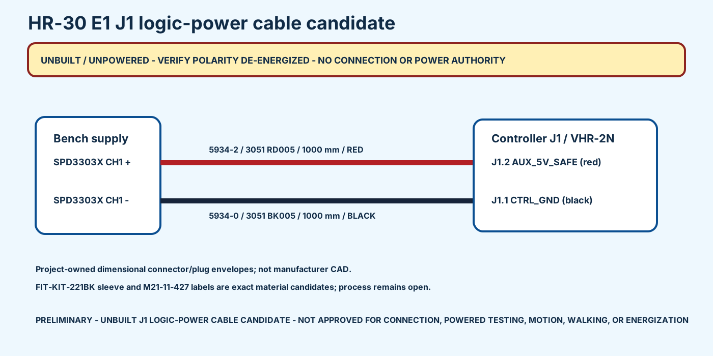
polarity-bound 22 AWG conductors
cut length for each conductor
native controller contacts
built, connected, or powered cables
complete fixture STEP · manufacturing cable STEP · assembly map
| Map | Supply | Wire | J1 contact | Net | Cut length |
|---|---|---|---|---|---|
| J1P-C01 | SPD3303X CH1 + | Alpha Wire 3051 RD005 | J1.2 | AUX_5V_SAFE | 1000.000 |
| J1P-C02 | SPD3303X CH1 - | Alpha Wire 3051 BK005 | J1.1 | CTRL_GND | 1000.000 |
The CAD fixes identity, polarity, cut length and the native J1 location. It does not release the JST crimp, Pomona set-screw torque, sleeve/label process, current/thermal limits, continuity/isolation/pull tests, voltage/current/OCP settings, grounding, connection, or power.
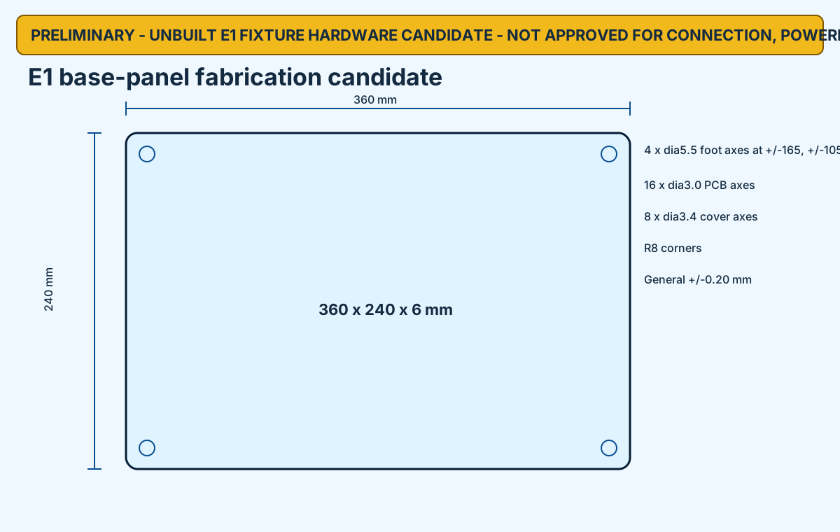
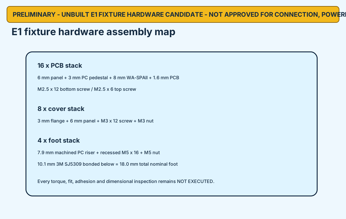
two-ended PCB support stacks with real pedestals and threaded standoffs
new physical cover fastener locations
18 mm riser-and-Bumpon foot stacks
fabricated or accepted hardware sets
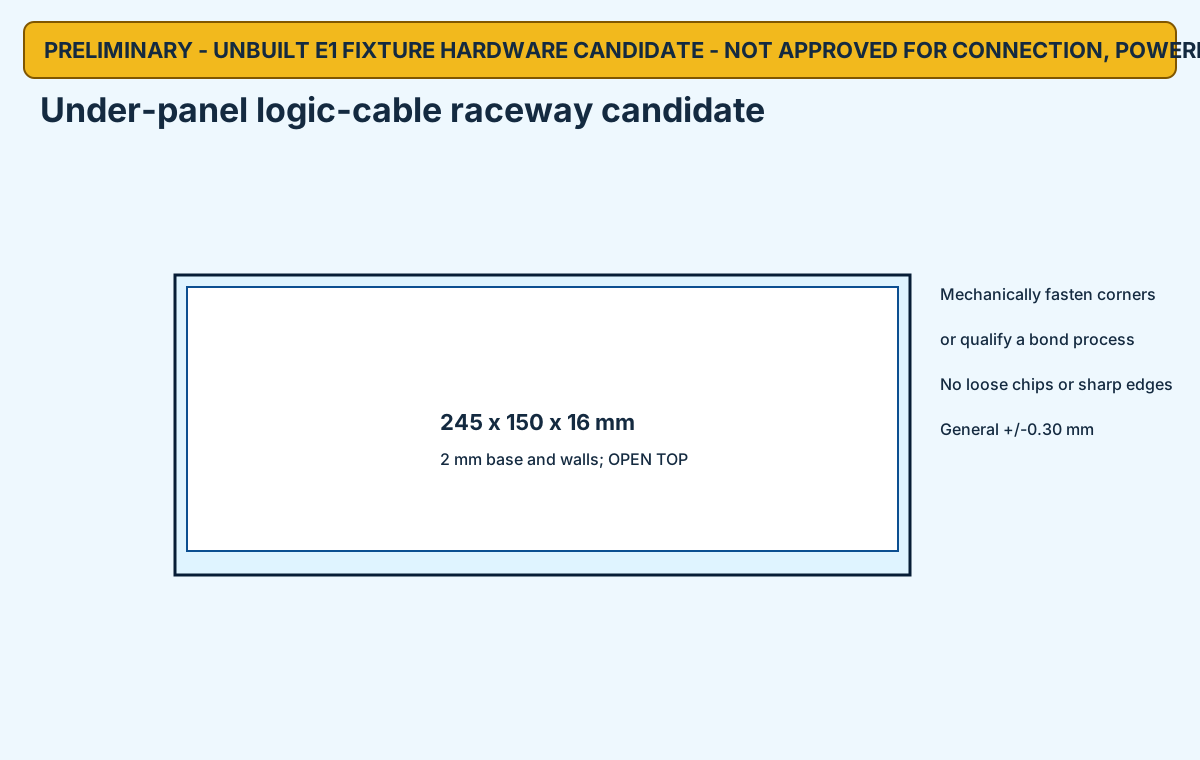
The base, covers, raceway, PCB pedestals and foot risers are dimensioned for clear SABIC LEXAN 9034 polycarbonate. Exact Wuerth, Essentra and 3M candidates are bound to the modeled stacks.
hardware STEP · base drawing · cover drawing · raceway drawing · assembly map
| Stack | Count | Candidate hardware | Validation |
|---|---|---|---|
| PCB | 16 | 970080155 + M2.5 x 12 / x 6 | Not executed |
| Cover | 8 | M3 x 12 + M3 nut | Not executed |
| Foot | 4 | M5 x 16 + M5 nut + SJ5309 | Not executed |
NO FABRICATION, CONNECTION, POWERED-TEST, MOTION, WALKING OR ENERGIZATION AUTHORITY.