MA-HN13-P10
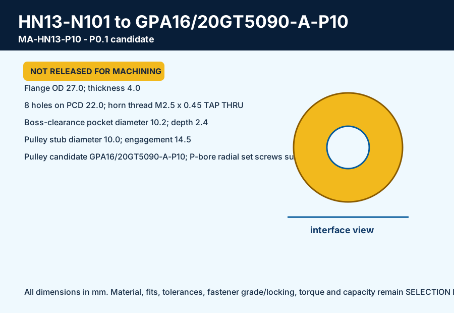
HN13 horn to GPA16/20GT5090-A-P10; 6 required.
Three motor-adapter families join exact HN12/HN13 horn patterns to P-bore pulley candidates. Two hollow output-shaft families provide shoulders and removable axial capture.
HN13 horn to GPA16/20GT5090-A-P10; 6 required.
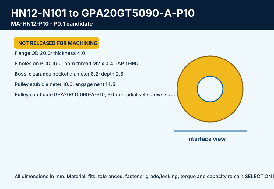
HN12 horn to GPA20GT5090-A-P10; 2 required.
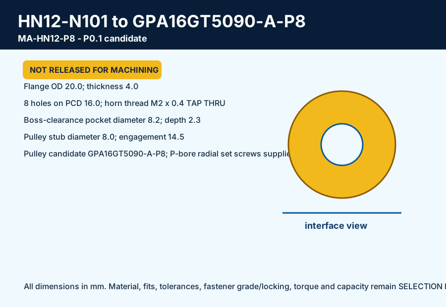
HN12 horn to GPA16GT5090-A-P8; 2 required.
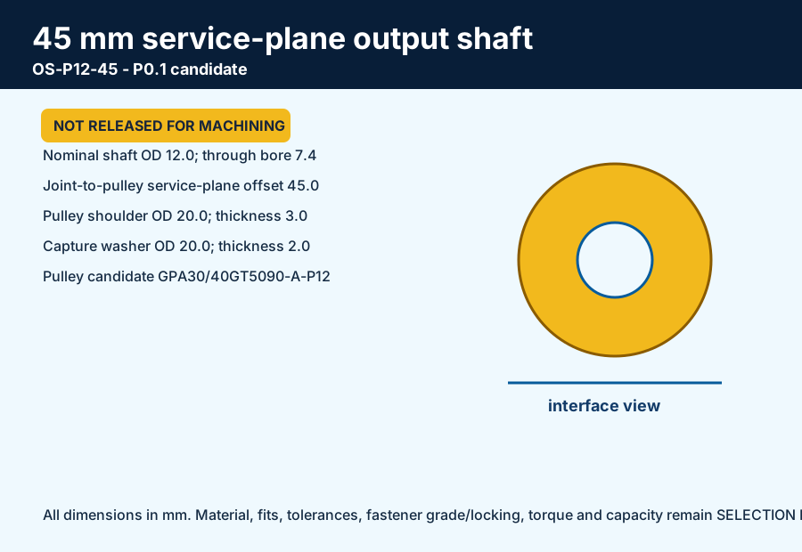
12 mm output shaft/shoulder/cap for 45 mm service-plane offset; 8 required.
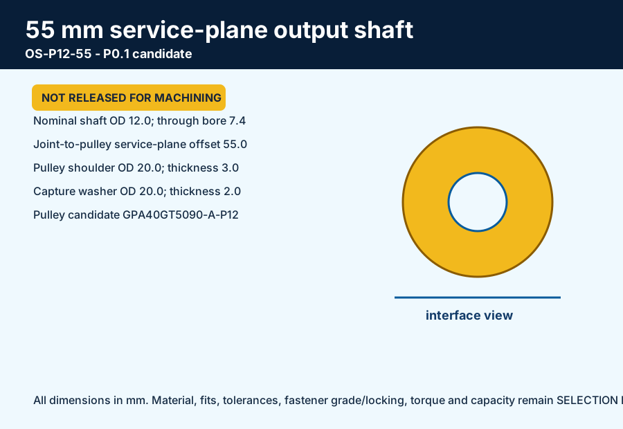
12 mm output shaft/shoulder/cap for 55 mm service-plane offset; 2 required.
The horn bolt circles, center-boss clearances, flange/stub geometry, nominal pulley bores, output-shaft shoulders, capture washers and per-axis allocation are editable source CAD. The selected MISUMI pulley suffix changes from H round bore to P round-bore-plus-tap so the catalogue supplies radial retention screws. The P0.1 model still withholds material, fit, runout, set-screw torque, bolt length/grade/locking, thread engagement, belt capacity, fatigue and physical-fit credit.