RS-LLEG
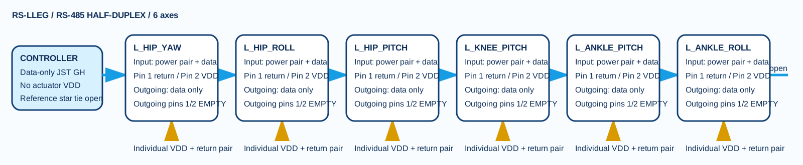
HR-30 · Whole-body P0.1
Every body corridor, actuator feed, data bus, joint loop and current ECAD terminal is accounted for—without pretending unresolved cable and protection choices are finished.
Gold rods are actuator-power centerlines; sky-blue rods are data/low-voltage centerlines. The translucent body is lightweight positional context. Rod diameter is illustrative and does not release cable OD, bundle clearance, or bend radius.
Download editable route STEP · Inspect the 113-solid CAD register
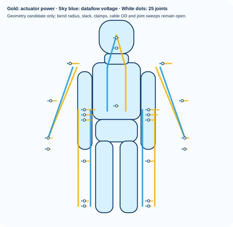
Select a data bus to filter the joint table; select it again to show all.
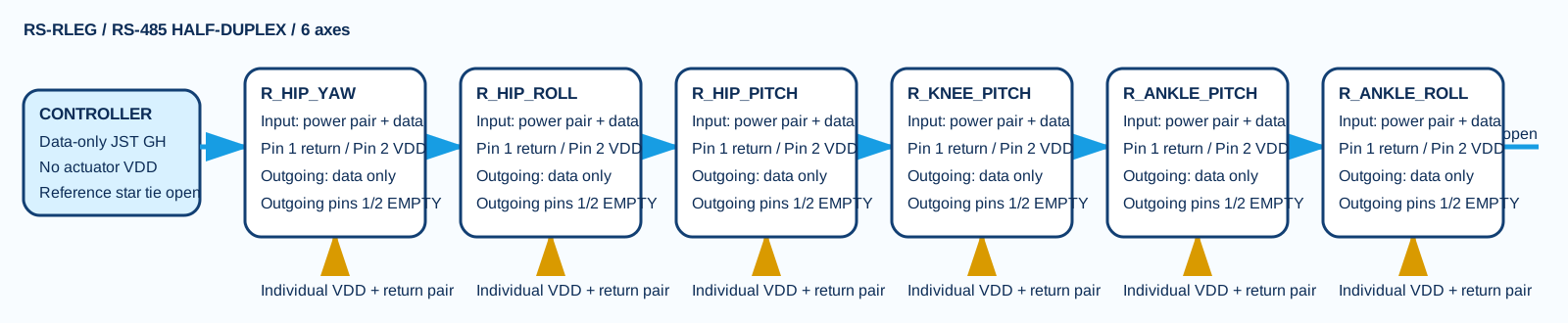
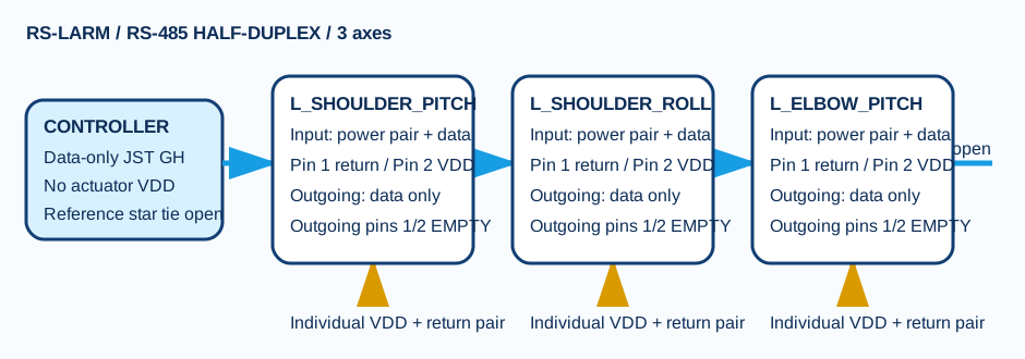
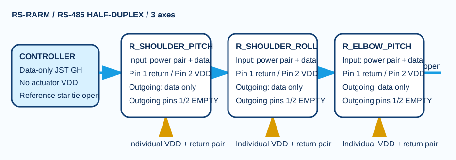
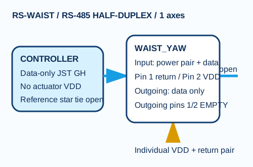
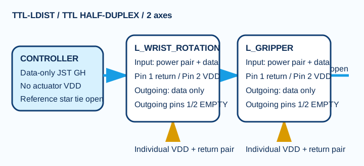
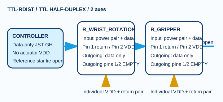
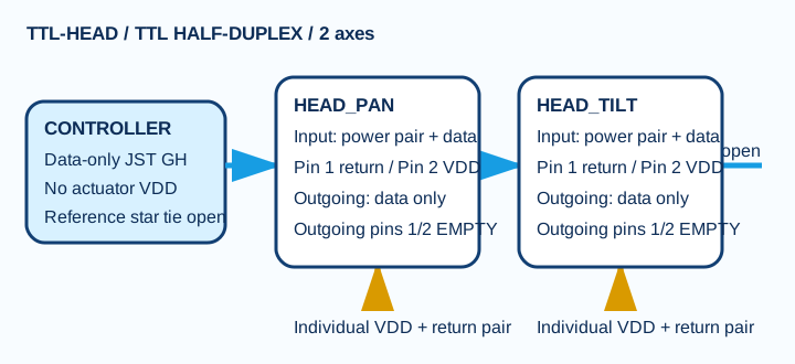
Each actuator receives an individual VDD/return pair. Inter-actuator outgoing connectors carry data only; GND and VDD cavities stay empty.
| Axis | Data bus | Actuator | Joint datum (mm) | Required moving segments |
|---|---|---|---|---|
| L_HIP_YAW | RS-LLEG | XH540 | (62.500,0.000,410.000) | 1 direct-power crossings LOOP-L_HIP_YAW-DATA |
| L_HIP_ROLL | RS-LLEG | XH540 | (62.500,0.000,390.000) | 2 direct-power crossings LOOP-L_HIP_ROLL-DATA |
| L_HIP_PITCH | RS-LLEG | XH540 | (62.500,0.000,370.000) | 3 direct-power crossings LOOP-L_HIP_PITCH-DATA |
| L_KNEE_PITCH | RS-LLEG | XH540 | (62.500,0.000,210.000) | 4 direct-power crossings LOOP-L_KNEE_PITCH-DATA |
| L_ANKLE_PITCH | RS-LLEG | XM430 | (62.500,0.000,55.000) | 5 direct-power crossings LOOP-L_ANKLE_PITCH-DATA |
| L_ANKLE_ROLL | RS-LLEG | XM430 | (62.500,0.000,35.000) | 6 direct-power crossings LOOP-L_ANKLE_ROLL-DATA |
| R_HIP_YAW | RS-RLEG | XH540 | (-62.500,0.000,410.000) | 1 direct-power crossings LOOP-R_HIP_YAW-DATA |
| R_HIP_ROLL | RS-RLEG | XH540 | (-62.500,0.000,390.000) | 2 direct-power crossings LOOP-R_HIP_ROLL-DATA |
| R_HIP_PITCH | RS-RLEG | XH540 | (-62.500,0.000,370.000) | 3 direct-power crossings LOOP-R_HIP_PITCH-DATA |
| R_KNEE_PITCH | RS-RLEG | XH540 | (-62.500,0.000,210.000) | 4 direct-power crossings LOOP-R_KNEE_PITCH-DATA |
| R_ANKLE_PITCH | RS-RLEG | XM430 | (-62.500,0.000,55.000) | 5 direct-power crossings LOOP-R_ANKLE_PITCH-DATA |
| R_ANKLE_ROLL | RS-RLEG | XM430 | (-62.500,0.000,35.000) | 6 direct-power crossings LOOP-R_ANKLE_ROLL-DATA |
| L_SHOULDER_PITCH | RS-LARM | XM430 | (90.000,0.000,590.000) | 1 direct-power crossings LOOP-L_SHOULDER_PITCH-DATA |
| L_SHOULDER_ROLL | RS-LARM | XM430 | (90.000,0.000,590.000) | 2 direct-power crossings LOOP-L_SHOULDER_ROLL-DATA |
| L_ELBOW_PITCH | RS-LARM | XM430 | (128.000,0.000,444.893) | 3 direct-power crossings LOOP-L_ELBOW_PITCH-DATA |
| R_SHOULDER_PITCH | RS-RARM | XM430 | (-90.000,0.000,590.000) | 1 direct-power crossings LOOP-R_SHOULDER_PITCH-DATA |
| R_SHOULDER_ROLL | RS-RARM | XM430 | (-90.000,0.000,590.000) | 2 direct-power crossings LOOP-R_SHOULDER_ROLL-DATA |
| R_ELBOW_PITCH | RS-RARM | XM430 | (-128.000,0.000,444.893) | 3 direct-power crossings LOOP-R_ELBOW_PITCH-DATA |
| WAIST_YAW | RS-WAIST | XM540 | (0.000,0.000,425.000) | 1 direct-power crossings LOOP-WAIST_YAW-DATA |
| L_WRIST_ROTATION | TTL-LDIST | XC330 | (133.000,0.000,299.979) | 4 direct-power crossings LOOP-L_WRIST_ROTATION-DATA |
| L_GRIPPER | TTL-LDIST | XC330 | (133.000,0.000,256.979) | 5 direct-power crossings LOOP-L_GRIPPER-DATA |
| R_WRIST_ROTATION | TTL-RDIST | XC330 | (-133.000,0.000,299.979) | 4 direct-power crossings LOOP-R_WRIST_ROTATION-DATA |
| R_GRIPPER | TTL-RDIST | XC330 | (-133.000,0.000,256.979) | 5 direct-power crossings LOOP-R_GRIPPER-DATA |
| HEAD_PAN | TTL-HEAD | XC330 | (0.000,0.000,650.000) | 1 direct-power crossings LOOP-HEAD_PAN-DATA |
| HEAD_TILT | TTL-HEAD | XC330 | (0.000,0.000,690.000) | 2 direct-power crossings LOOP-HEAD_TILT-DATA |
Moving CF130 no longer terminates directly into JST EH. Each of the 25 branches now ends the moving cable at Molex 430250200 / 430300001, mates to panel-mounted 430200200 / 430310001, then continues through a restrained Alpha Wire 3051 pigtail to the actuator.
The parts are exact candidates, not released selections. CF130 core OD, bracket/fastener geometry, pigtail length, crimp qualification, derating, pull, temperature-rise and flex tests remain open.
Each actuator now has its own positive/return power pair. The P0.1 split-harness candidate combines that pair with incoming data at the actuator input housing, while the outgoing housing populates data contacts only. GND and VDD cavities remain empty so power is not daisy-chained through preceding actuator connectors.
The 71.88 A figure is the arithmetic sum of momentary 12 V stall-current endpoints—not a normal-load forecast, fuse rating, cable rating, or permission to energize.
Pinouts are verified; the cable assembly is not. ROBOTIS lists 21 AWG DYNAMIXEL wire, while JST's EH catalog limits the listed SEH-001T-P0.6 contact to AWG 22. ROBOTIS also writes EHR-03/EHR-04 while JST's own catalog table writes EHR-3/EHR-4. Neither discrepancy is silently normalized.
U2D2 remains a one-segment commissioning candidate only. It is not the final eight-segment controller. The 10 A U2D2 Power Hub is rejected for whole-body and leg power aggregation.
verified device interfaces · commercial cable review · open manufacturer discrepancies
route segments · route points · direct-power crossings · route CAD · axis bindings · actuator chain map · individual power pairs · serial data links · all connector cavities · cable cores · equipment interfaces · logical terminals · derating inputs · inspection/tests · open selections
physical power routes bound to pooled whole-body duty.
bus-domain loss and peak/RMS screens.
power-corridor bundle obligations.
released hot ratings or executed thermal tests.